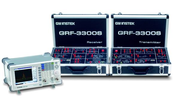
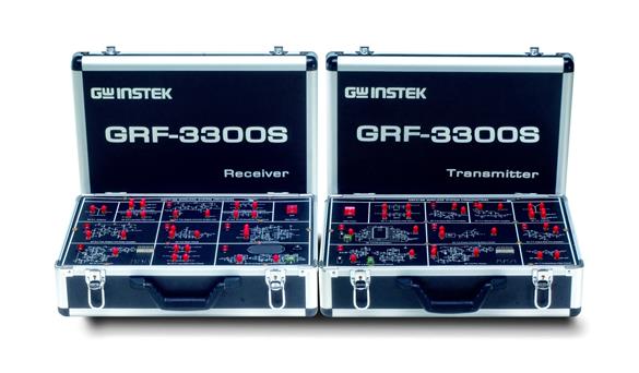
GRF-3300无线射频&频谱分析仪教育训练系统产品详细规格
Training Contents | |||
Sections | Theory | Experiment | Related Applications |
The Fundamentals | Impedance matching network: L-type, π-type, T-type | Theory exining | RF Component Test |
Antenna | Antenna parameter, antenna structure, antenna type | Frequency response | Antenna Design |
Attenuator | Attenuator parameter, attenuator type, attenuator design | Attenuation characteristics | When the Signal is Too Big |
Low Noise Amplifier | LNA parameter, 1dB compression point, LNA structure | Input and output return loss, amplifier gain, 1dB compression point | Small Signal Enlarged |
Preamplifier | Preamplifier type, preamplifier structure | Input and output return loss, amplifier gain, 1dB compression point | Small Signal Enlarged |
Power Amplifier | Power amplifier frequency characteristics, bias circuit, power amplifier parameter, power amplifier structure | Gain flatness, 1dB compression point, fundamentals to harmonics ratio | Power Enlarge |
Filter | Filter parameter, filter structure: Butterworth, Chebyshev | Input/output return loss, insertion loss | EMI filter Design |
Mixer | Mixer structure, mixer parameter, mixer type | Conversion gain, 1dB compression point, isolation | TV Tuner |
Phase Locked Loop | PLL structure, frequency synthesizer, PLL controller, loop filter, design a PLL | Frequency response/modulation | Signal Generator |
Audio Processor | Audio compression/decompression circuit | Pre-emphasis, compression characteristics, expander and de-emphasis, decompression characteristics | Wireless Microphone |
Modulation | Design and implement a modulation circuit | Frequency modulation | Remote Controller |
Demodulation | Design and implement an FM intermediate frequency demodulation circuit | IF modulation, RSSI output | Broadcasting |
Transmitter | Transmitter parameter, transmitter structure | Transmission spectrum | Radio Set |
Receiver | Receiver parameter, receiver structure | Receiving signal spectrum, demodulation waveform | Radio Set |
Voice Demo | Combine with transmitter & receiver circuits | Voice communication system | VoIP |
Microstrip Line Filter | Transmission line basics, stepped-impedance LPF, coupled line BPF, optimized HPF | Insertion loss | RFID |
POWER SOURCE | |||
| AC 110V or 220V, 50/60Hz | |||
DIMENSIONS & WEIGHT | |||
| GRF-3300S | 428(W) x 90(H) x 303(D)mm for Transmitter & Receiver, Approx. 8.4kg | ||
| GRF-3300K | 560(W) x 170(H) x 530(D)mm, Approx. 7kg | ||
Ordering Information | |||
| GRF-3300S Package | Including Spectrum Analyzer GSP-830 + Tracking Generator(TG), RF Training System GRF-3300S | ||
| GRF-3300K Package | Including Spectrum Analyzer GSP-830 + Tracking Generator(TG), RF Training Kit Sets GRF-3300Kning Kit Sets, 22 modules (12 for receiver and 10 for transmitter systems) | ||
| GRF-3300S(*) | RF Training System, Two Systems (Transmitter and Receiver) | ||
| GRF-3300K(*) | RF Training Kit Sets, 22 Modules (12 for Receiver and 10 for Transmitter systems) | ||
| (*)All GRF-3300S/K experiments are based upon GSP-830, we can't guarantee the result almost has its similarity by using other spectrum analyzers of their kinds. | |||

